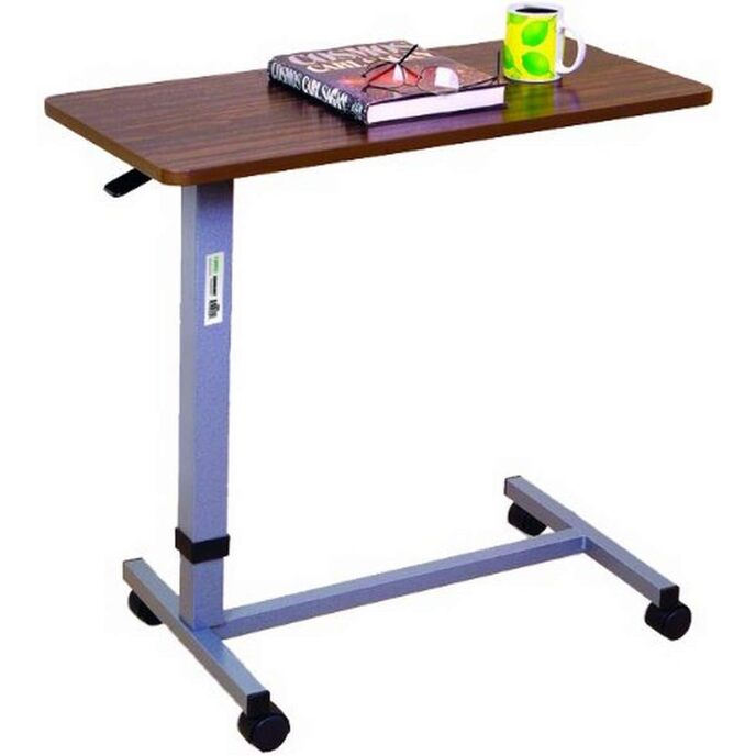
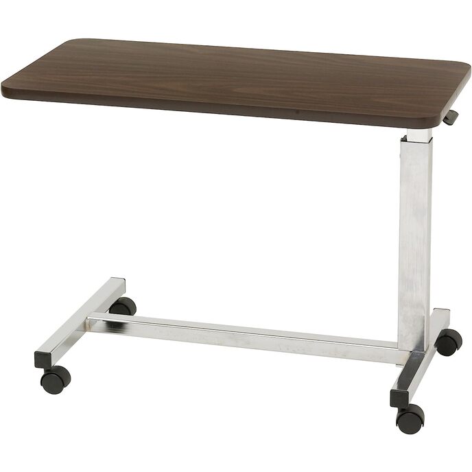
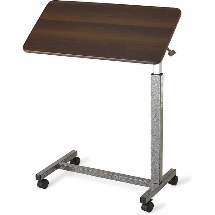
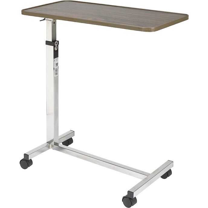
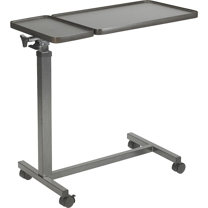
I have owned and used this table daily for several weeks now and find it to be as advertised and just what I needed. However.... Assembly really is easy as many of the reviews say, but the short instructions are full of errors and will confuse anybody at first, but especially those not mechanically inclined - like my wife, who tried very hard to assemble it while I was nearly completely incapacitated - but could not. For example, in the instructions provided with my table, while part numbers listed on the parts card (a card to which the smaller parts are attached) matched the Assembly Instructions, they did not match the Parts List or the Assembly Diagram components of the original instructions. So I re-wrote the instructions correcting the errors I found. See below. If you use my re-write, you still need to refer to the Assembly Diagram and Warnings of the original instructions. Since the manufacturer changes designs and instructions all the time, while these modified instructions worked for me, they may not work for you. You should consider the manufacturer's original instructions to be authoritative and use my version only at your own risk. I cannot be held responsible for installation failures or damages to your table. Warning: Do not remove the black screw on column until table is fully assembled and in a standing upright position. If you do, you will likely render the height adjustment permanently inoperative. Parts Card: Parts labeled '6', two lock washers and two screws, are missing from the card. They are not needed for this model. Otherwise, everything else is correctly labeled. Parts List: 1. Table top - OK 2. Column Assembly - OK 3. Trip lever - OK 4. 1/4-20 bolt & nut (1 each). These connect the Trip Lever to the Column Assembly. Labled OK on the Parts Card, but should be 15 in the Assembly Diagram (probably). 5. Bracket Top to Column. This is not a bracket but the outer tube into which the tube attached to the Column Assembly is inserted. 6. 1/4-12 Bolts (2). Not included with my table, and not required either. 7. Base - OK 8. Casters with brake - OK 9. Casters without brake - OK 10. Bolt Sleeves (2) - OK 11. Bolt Plate - OK 12. 3/8-15x2 Bolts - OK 13. Black Screw - OK 14. Chrome Screw (Hex-Head Screw) Not a Hex-Head Screw and even though there is one on the parts card, there is already one installed as per the photo labeled 'Do Not Remove Bottom Screw' on the original instructions. 15. Screw set - Probably number 4 on the Parts List. Otherwise I couldn't identify this entry. 16. Triangular knob. Not to scale on the Assembly Diagram. The knob is much larger than what is shown. Otherwise OK. 17. Rotatable screw - OK Assembly Instructions: 1. Open the box, remove and lay out contents on a level surface. 2. Install the Trip Lever (3) into its slot in the Column Assembly (2). The rounded side should face the tube. Make sure the Trip Rod (inside the column) rests against the flat side of the Trip Lever. Insert the Bolt & Nut (4) through the holes in the Column Assembly and the Trip Lever and fasten. Do not over tighten. It doesn't matter which side you put them in. 3. Insert the tube of the Column Assembly into the larger tube already attached to the table top at the end labeled '4'. Insert the Rotatable Screw (17) into the larger tube at the end labeled '5' as shown. Secure the Rotatable Tube to the assembly using the Triangular Knob (16). This is the table's tilting mechanism. 4. On the base of the table (7), place two bolts (12) through bolt plate (11) and 2 bolt sleeves (10) as shown in the diagram and tighten securely. 5. It makes a difference which side of the base the casters (8, 9) are installed. Make sure you install them as shown in the Assembly Diagram. Once you have properly lined up the casters' pivot pins into their respective slots, apply firm pressure with both hands to seat them fully. 6. Place the base upright on a level surface and insert the Column Assembly into the base's upright as shown in the Assembly Diagram. 7. Only at this point and after you are confident that the rounded side of the Trip Lever is facing the table top and the Trip Rod is facing the flat side of the Trip Lever should you remove the black screw. Removing the black screw will remove internal tension and allow that tension to be applied to the Trip Rod. If you remove the black screw at any other point in the installation, you may render your table inoperative. CAUTION DO NOT REMOVE THE BLACK SCREW ON COLUMN UNTIL TABLE IS FULLY ASSEMBLED AND IN A STANDING UPRIGHT POSITION (CHROME SCREW WITH HEX-HEAD ON COLUMN SHOULD NOT BE REMOVED). Other Notes: With the exception of the instructions, I am happy with this purchase. There is some wobble in table that makes writing using pen and paper uncomfortable, if writing furthest from the desktop's stand. My solution is to write closer to the stand end. I don't have any difficulty using a laptop with the table. While I thought raising the table to be a bit touchy, it is as advertised. The tilt feature is easy to use and once locked into position, stays there.