Reliance Controls 31410CRK Kit interruttore di trasferimento generatore Pro/Tran 10 circuiti 30 Amp, grigio

Brand:Reliance Controls

3.7/5

871.90

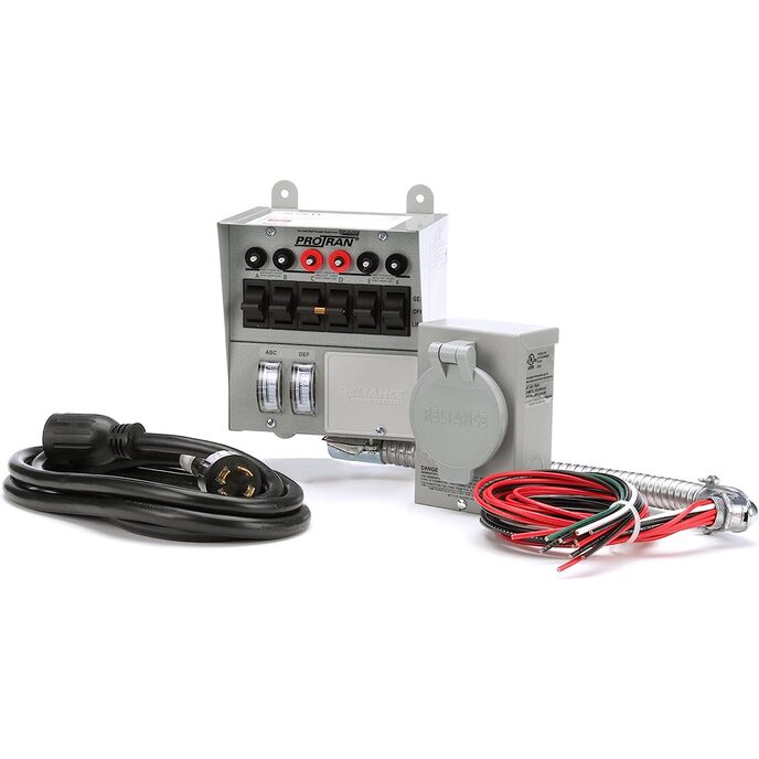
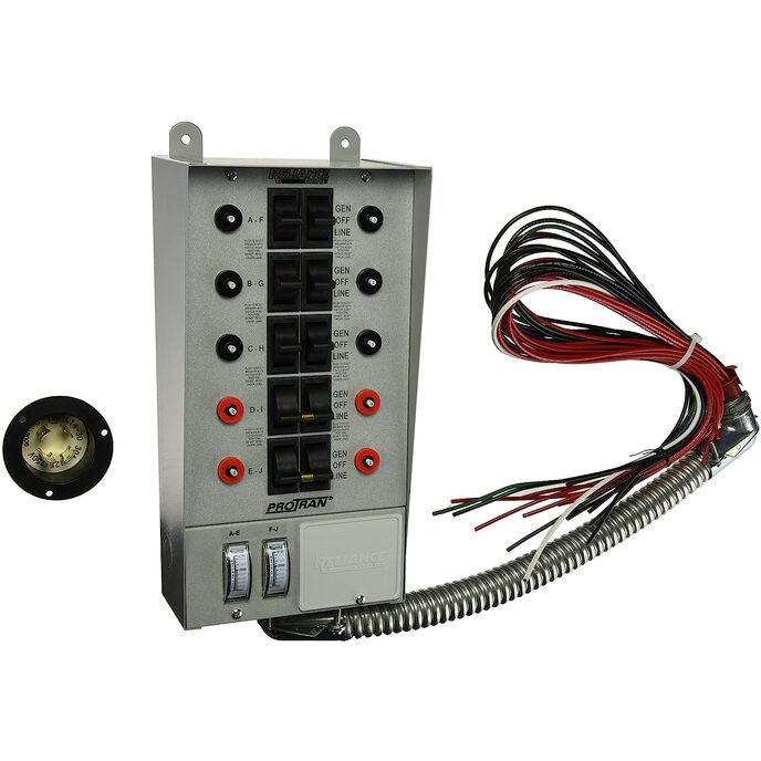
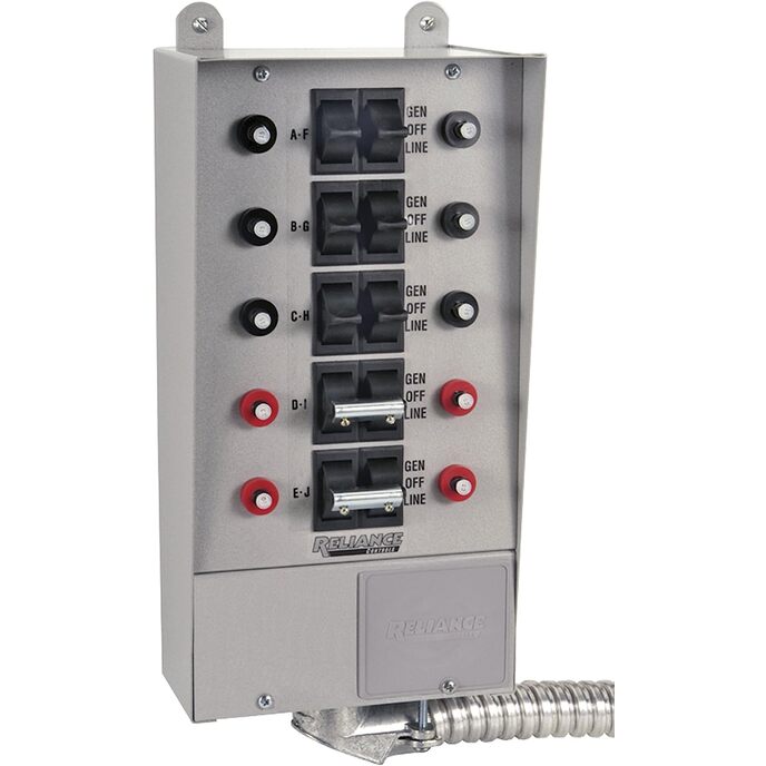
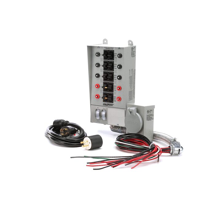
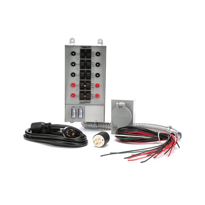
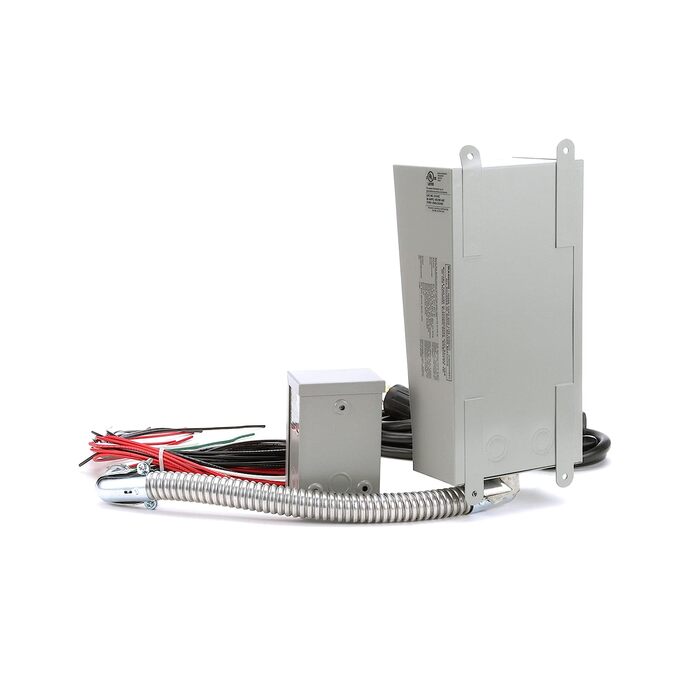
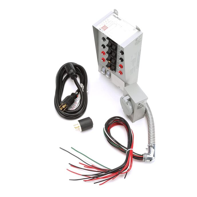
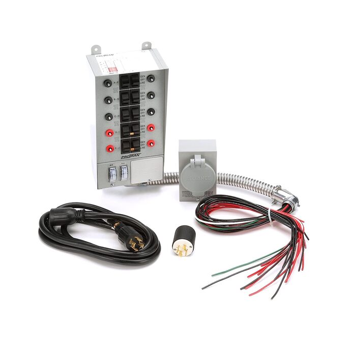
DESCRIZIONE PRODOTTO Il kit interruttore di trasferimento Pro/Tran 30 Amp 10 circuiti Reliance Controls 31410CRK ha tutto il necessario per completare facilmente l'installazione di un interruttore di trasferimento generatore portatile in una casa o in ufficio. Lo scopo di un interruttore di trasferimento è quello di collegare una fonte di alimentazione secondaria, come il tuo generatore portatile, ai circuiti della tua casa o dell'edificio che sono cablati nel sistema elettrico. Pertanto, è progettato per consentire al sistema di cablaggio dell'edificio di accettare la piena potenza di un generatore portatile, che può far funzionare più apparecchi e dispositivi elettrici durante un'interruzione di corrente. L'interruttore di trasferimento garantisce l'utilizzo sicuro dell'alimentazione di riserva durante un'interruzione di corrente senza doversi preoccupare di alimentare nuovamente la linea di servizio. In una situazione di emergenza, questo kit può fare la differenza. Dal 1909, Reliance Controls Corporation ha apportato più innovazioni di qualsiasi altro singolo produttore e ha ottenuto oltre 85 brevetti su commutatori manuali, interruttori orari e accessori. Reliance Controls Corporation è specializzata nella produzione di un'ampia varietà di prodotti elettrici. La linea di prodotti principale è costituita da orologi e controlli per impieghi gravosi, accessori per generatori, commutatori di trasferimento e pannelli di trasferimento per generatori portatili. E dopo oltre un secolo di innovazione, Reliance Controls Corporation si è costruita un'invidiabile reputazione per l'alta qualità, l'ingegneria superiore e l'eccezionale servizio clienti. AMAZON.COM Il kit dell'interruttore di trasferimento da 30 Amp a 10 circuiti della Reliance Controls Corporation è un kit chiavi in ​​mano completo con tutto il necessario per realizzare un'installazione professionale dell'interruttore di trasferimento in casa o in ufficio. È progettato per consentire al sistema di cablaggio dell'edificio di accettare la piena potenza di un generatore portatile, che può far funzionare più apparecchi e dispositivi elettrici durante un'interruzione di corrente. Utilizzare questo interruttore di trasferimento per generatori fino a 8000 watt dotati di prese di alimentazione NEMA L14-20 o L14-30. Il kit include un commutatore di trasferimento di fiducia lato carico precablato a 6 circuiti da 30 Amp con wattmetri; Scatola di ingresso del cavo di alimentazione per esterni da 30 Amp, un cavo di alimentazione del generatore da 30 Amp da 10 piedi con estremità L14-30 e un'estremità del cavo L14-20 aggiuntiva per i generatori più piccoli. Questa unità è elencata cUL1008 ed è coperta da una garanzia di 5 anni.

Dispone di un robusto armadio in acciaio verniciato a polvere. sei fori combinati e altro ancora. Circuiti unipolari massimi: 10 / Circuiti bipolari massimi: 5. La frusta flessibile da 18 pollici si attacca facilmente al centro di carico. Progettato specificamente per generatori fino a 7.500 watt massimi di funzionamento. Il comodo kit dell'interruttore di trasferimento, ideale per i circuiti e le esigenze di cablaggio multiplo, è realizzato anche per un'installazione rapida e affidabile in applicazioni sia residenziali che commerciali.
Brand Reliance Controls
Connector Type Plug In
Contact Type Normally Closed
Country of Origin China
Current Rating 30 Amps
Is Discontinued By Manufacturer No
Item Dimensions LxWxH 7 x 4.5 x 13.75 inches
Item model number 31410CRK
Manufacturer Reliance Controls
Material Other
Operating Voltage 120 Volts
Operating Voltage 120 Volts (AC)
Operation Mode ON-OFF-ON
Product Dimensions 7 x 4.5 x 13.75 inches; 1.91 Pounds
Switch Type Toggle
Terminal Spst

3.7

9 Review
5 Star
82
4 Star
11
3 Star
2
2 Star
2
1 Star
3

Scrivi la tua recensione

La tua mail non sarà pubblicata. Tutti i campi obbligatori sono segnati con*

Scritto da: Rony
Pro/Tran 10 circuit kit review
I consider this product to be excellent. The transfer switch and all of the supporting peripherals are top of the line. I would however, provide the following caution. I would advise that anyone who is not an experienced electrician, watch the available video on how to connect your transfer switch to your existing circuit breaker panel. Once this is done understand that the video shows an ideal situation that demonstrates the installation procedure. Your situation will probably be different in some way. In my case here is what I encountered: 1) The circuit breaker panel in the video is very large with a lot of room to add extra wires. My circuit breaker panel (100 Amp) is small and fully populated with breakers. As a matter of fact my panel had three ½ sized breakers where to circuits are controlled from what is normally designed for a single size 120 volt breaker. This added to the population of wires in the panel and made the wiring tight to start with. When wiring the 22 additional wires used by the transfer switch into the breaker panel the space was very limited. I had to be very careful to choose the proper wire routing to make everything fit properly. Doing so made the final product work as advertized. 2) The ½ size breakers provided and additional challenge. Two wires come into this style breaker. One wire in front of another one. Even if I had taken the front wire off, I couldn't get at the back wire because of the interference of other breaker wiring. This necessitated popping the breaker out of the panel to accomplish the wiring. Once I did this, all went well. 3) Problem number three: In addition to the circuit breaker panel being large in the demonstration video, it is also a panel that hangs on the outside of a wall. My home is a raised ranch and doesn't have a basement. Because of this, the circuit breaker panel is located in the laundry room and is recessed into the wall. This meant that there was no convenient way to get at a knock out to install the cabling that comes from the transfer switch to the breaker panel. Luckily, there was one and only one knock out on the back of the circuit breaker panel. Even luckier was that the back of the panel faced a garage wall. To find that knock out from the garage side of the breaker panel was a challenge. I took detailed measurement in my laundry room and then calculated what I thought was the location of the knock out behind the wallboard in the garage. I drew a two inch circle to cut out on the wallboard and was delighted when I could see half of the knock out showing. Enlarging the cut out by an inch gave me the access I needed. I did a couple of things to ensure my safety. Because my circuit breaker panel does not have a main breaker switch on the panel, but rather it is located outside the house on the same panel that contains the meter that monitors my electric usage, I turned that breaker of and put a small lock on the cover to the switch. This ensured that no one would turn on the breaker while I was wiring the transfer switch into the breaker panel. I also used an electrical sniffer ($15.00 at Home Depot) to verify that all power was off inside the breaker panel. SAFETY FIRST Another thing I did was to pare up the individual wires before I started wiring - black A with red A, black B with red B etc. I did this by using small tie wraps. What this did for me was to ensure that when I went to wire a circuit, let's say H, I would cut the tie wrap from red and black H wires. At this point, the only two wires that weren't tie wrapped were red H and black H. This meant that I wouldn't accidentally wire the red H wire into a beaker and a black I wire to the wire removed from the breaker. After completing all of the circuit breaker wiring, I turned on the main breaker and one at a time moved the individual transfer switches to the LINE position. This verified that each circuit was working properly and was assigned to the correct switch. The only other thing needed to complete the installation was to wire the remote power input box to the transfer switch. This was strait forward with no problems. The only thing to watch for here to make sure that the meter pick-up coils remain on the black and red wires as they are when the box is shipped. Also, when joining the input power wires to the transfer switch wires using wire nuts, keep that wiring to the right side of the box so as to leave space for the meters when putting the transfer switch cove back in place. All in all, it was a fun task and the finished product worked very well. I was even happy when I shut off all power to the house, fired up the generator, and powered the house from the emergency generator. From the time I took the generator out of the garage, started it up and connected the generator cable to the remote input box and started supplying power to all of the circuits I selected to wire up, it was about 3 ½ minutes. I could even watch the meters and see when loads (such as the refrigerator or freezer compressors) were coming on and off. Watch the videos, do your homework, and have a plan in place before you order this product. If you do this, you'll be quite satisfied with the end result. Be advised that the one hour estimate to complete the wiring of the transfer switch to the circuit breaker panel as shown in the videos turned into 3 1/2 hours because of the problems described above. This is a very good product. I highly recommend it.
Scritto da: Lemon Twist
Easy to install and easy to use.
After a couple of years with several day long, or longer, power outages we decided to install a backup system. We bought the transfer switch capable of supporting 10 circuits from Amazon. Delivery took about a week and the unit was well packed with no damage. The unit is solid and heavy duty. Installation was very easy and took a total of 4 hours, start to finish. It took longer to run the cable to the outside connector plug than anything else. After carefully mapping my current circuit breakers so that I knew exactly which breaker affected which lights, outlets, and etc. it was time to decide which circuits we would backup. Since the transfer switch supports 240 volt connections and our generator is capable of 10KW peak we were able to divide and balance the load across the two 120 volt legs based on normal and peak power requirements. It took awhile to get the balance figured, then we made a map identifing each circuit breaker and each backup circuit. The drawing is now covered with plastic and on the wall next to the main panel. We also wrote out detailed instructions on how to activate the system and how to transfer back to commercial power. Pretty easy but when the power is out you need to make sure you don't make simple mistakes, like not grounding the generator for example. I know most of what I have said doesn't really address the product but it is useful information for anyone contemplating such an installation. The transfer switches (there are 10) are rugged clearly marked and each has its own circuit breaker. Each circuit is clearly identified by a letter A through I. Using a tape machine I added labels showing which circuit each lettered transfer switch connected. A very nice feature is the power meter for each leg of the 240 circuit. If you have an imbalance you will see it and be able to turn switches off to see the effect. In the end, if you didn't get the balance correct the first time, you can drop circuits to keep running and then decide how to move circuits later. The wires were all clearly marked and were stranded copper so they were easy to route. As I wired each circuit the following procedure was followed: 1: Main power off. 2: Selected circuit off. 3: Red wire to circuit breaker. 4: Black or Red hot wire from breaker connects to the black wire from the transfer circuit with a wire nut. 5: Main power on. 6: Checked that power was still off at selected circuits in the house. Lots of running around .... 7: Selected breaker to on. 8: Checked that power was returned to the selected circuits in the house. 9: Repeat steps for remaining circuits. I could have simply wired all the circuits once the main power was removed but by doing it this way I double checked my initial mapping of the house. In my case everything was perfect. If I had made a mistake in my map it would have been more difficult to fix the problem later. After grounding the generator I connected the umbilitcal to the 110/240 connection on the side of the house and to the generator. I started the generator and let it run for 5 minutes to get warmed up. Inside the house I started a process where I transfered a cirucit, observed the power meter, and checked that I had power in the house. Everything worked perfectly and neither power meter on the tansfer box was showing high use. Waited for the furnace to kick on and still not too much power use. On the same leg of the 240 volt circuit I operated the garage door and did not overload the side. Now I knew both of these cirucits could operate simultaneously. I repeated several scenarios using the Televisions, computers, microware, and even the coffee pot. Everything worked fine. I knew that I could not power up everything or I would overload the generator and likely kick the main breaker. We don't operate the coffe pot at the same time we are using the microware, for example. We don't leave lights on in areas of the house we are not using. We do have several low power night lights in the house. All in all, a great system that works very well providing you have properly balanced the load and not tried to power up too may things that require a lot of power. Be especially careful of those things that require a higher peak power at startup. These are usually things like a furnace with a motor that needs some grunt power in the beginning but less once it is running. These can be pretty high, 2KW or so, and if they start at the same time they will trip the generators breaker. Be conservative and you will weather a storm without commercial power with ease. This box comes in several sizes and you should get one that matches the capabilities of your generator. By the way, I did the work myself but had over-the-shoulder help from a friend that is a licensed electrician. My signature says Lemon Twist in Manheim Germany.... I came back from Germany in March so all of this was done in the USA.
Scritto da: Amazon Customer
Worked out very well
The installation went very well. I bought the drywall mounting kit bracket along with the transfer switch. I used a drywall undercut dremmel tool to cut holes in the drywall. The bracket screwed into a stud on the side. I bought a 1.5 inch and a 2 inch wood hole bits. You have to drill 2 holes in the studs to allow the wires to pass from the transfer switch to the electrical box and from the outside wall to the transfer switch. I drilled one hole at the top to get into the ceiling. It took 3 drywall cuts to do the job. I used 1/2 inch emt conduit to run the generator outside box connection. The wires were well labeled with numbers. It allowed for 220 vac or 120 vac but you have to have a 220 vac generator if you want to control air conditioning. My generator was 30 amps one phase so the 2 120 vac hots had to be connected together. I bought a rv 3 pos to house 4 pos adapter. I had one hole on the bottom right that did not screw into mounting bracket. I tested it today. Everything worked. I used 10 -120 vac switches. I took out the 220 vac switch bars. It would help to have extra 15 amp circuit breakers to use instead of the 20 amp ones. I was impressed with the operation of the switch after I completed everything. It was a positive experience but I took my time to plan it well. There was a caution to Only use a generator that has a floating nuetral. Dont hook to a neighbors electrical system, for test, because the phases might not match. The instructions were well written and easy to follow. I did not need to call the tech support.
Scritto da: JDDan
Flex Conduit too small
The only issue I had was fitting all of the wires through the flexible conduit. It’s a really tight fit.
Scritto da: 1keypurcahser
Quality Box / Peace of mind for storm season
First off, I am not a Journeyman Electrician but do have a bit of knowledge concerning electrical. Placement of xfer switch was a little challenging as I had to mount within an interior wall next to panel, else no room otherwise. Wires are clearly marked and instructions easy to understand. Take your time when planning location of switch as you want to avoid moving 2-3x after finding wires too short. Overall I spent 3hrs cutting drywall and installing 3/4" backer board to mount switch to. Actual connection of switch to panel and routing of 10/4 cable down through floor to outside wall outlet for generator was easy. Make sure you tighten breaker and panel lugs snugly. I used all six 15amp breakers to provide power for: fridge, water heat trace, lights/plugs, deep freeze, furnace balanced on either side of switch Observed power draw when running: Fridge 300-400 watts NG Furnace 500-600 watts Heat trace 200 watts (was a smaller heat trace on 15 foot exposed water line) Lights and Plugs 500-700 watts Freezer 350-400 watts If you have a bit of skill with trades work and take your time I see no reason why you couldn't tackle this yourself. Couple items of caution: - power off main power while working to install xfer switch leads inside power panel (confirm power off with voltmeter) - ensure you remove correct size knockout for wire lead (if not using knockout cutters) - ensure lugs are tightened securely and marrets (wire nuts) are tightened securely (pull on wires to ensure mechanically secure) - be careful with amp gauges when pull xfer switch cover off, they are delicate - measure twice, cut once on all wires - Ensure cable entering outlet box (outside) and xfer switch (inside) secured mechanically. I used weathertite flex (bx) 10-4 to establish connection. I suppose you could use EMT and pull individual conductors, but seemed like a lot of work.
Scritto da: Daphne Blake-Leavitt
Fairly easy to follow instructions
We were disappointed that there are only 6 110 volt circuits and surprised to find 2 220 volt circuits which are virtually useless to us as we don't have the right wiring for our house for the 220. However, after some investigation, it seems that for whatever reason they are all like that. So if you buy this to use a generator in a house wired with 10/4 NMD wire which is standard in Canada, just know that you will only be able to hook up 6 circuits to provide electricity with your generator.
Scritto da: C. Mudle
Not Approved in Nova Scotia
This looked like a really easy unit to install at a great price including generator cable and socket. I had some questions about the breakers and Canadian approval so asked a friend who is an electrical inspector. 1) It is not approved in Nova Scotia because the neutral must be switched, a 3 pole transfer switch is required, a 2 pole transfer switch like this is not approved. 2) The recommend method of installation requires splices in the main panel, this is a grey area some inspectors may OK it, others would require a separate box complicating installation, in any case 1) applies. Since I have an electrical background I asked why Nova Scotia is one of the few north American jurisdictions that requires a switched neutral on small generators. The first reason was that the is no control over weather a floating neutral or bonded frame neutral generator is plugged in at some future time, so full isolation is required. Second they insist that under certain fault conditions a non isolate neutral could pose a risk to lineman, apparently most of north America doesn't doesn't recognize this risk or doesn't value their lineman as much as us. The last thing any one wants to do is risk a lineman's life, so reluctantly I have returned this unit and are having a generator sub panel with 3 pole transfer switch installed.
Scritto da: Steve M
Reliance needs to up their QC game!
Arrived with a broken fuse. Contacted Reliance and replacement is on the way. As for their Quality Control. Checked and matched all the wires to find that E and F had an issue. Instead of having a black and red “E” I had 2 black “F” wires. (See photo). I was able to test the wires and figure it out, but that could potentially be a hazard. I have read a few reviews on here with breakers tripping when plugging the generator into the switch and customer service not being able to solve this problem. I’m wondering if this may be the problem. For such an expensive switch they seriously need to up their game when it comes to QC.
Scritto da: bikerfan
DO NOT BUY!
I purchased this transfer switch after being led to believe it could be installed here in Canada. It took a couple months before I got electricians booked (due to backlogs) out to install it. This panel does not meet Canadian electrical code can't and now Amazon has blocked my returning it. My next step is to call Visa to try and get my money back. PS- Amazon went to bat to get my money back less 15% restocking fees (I surmise)...kudos to them for working it out for me as I thought I had it figured out as a layman...folks! Consult an electrician and local codes as Reliable Controls makes several models - some of which cannot be connected to your panel legally!

Prodotti correlati

Scopri il nostro network internazionale

Spediamo in 28 paesi, oltre 200.000 prodotti. Resta aggiornato, iscriviti alla newsletter.

Shopping Cart