sourcing map AC 110V 8P 0-60 Minuti Intervallo Ritardo Regolabile Relè Temporizzatore AH3-3 + Base

Brand:uxcell

3.4/5

41.29

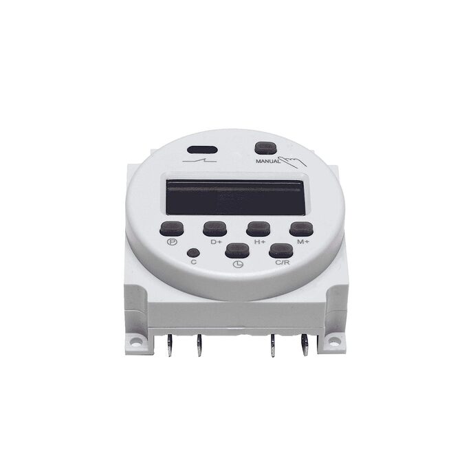
Ritardo all'accensione e temporizzazione. Con grande manopola di impostazione dell'ora trasparente per impostare facilmente l'ora, terminale a saldare a 8 pin per l'installazione. Relè di ritardo utilizzato nel sistema di automazione industriale e nelle apparecchiature meccaniche per ritardare il componente. Il relè è una sorta di interruttore elettrico automatico, quando viene fornito con un valore di ingresso, come un segnale elettrico, magnetico, luminoso o termico, trasferisce automaticamente il circuito controllato e apporta un cambiamento brusco, quando il valore di ingresso diminuisce fino a un certo punto, lo farà riprendere allo stato precedente e riportare il circuito controllato allo stato precedente. L'indicatore LED mostra l'alimentazione e lo stato di uscita.

Relè di ritardo utilizzato nel sistema di automazione industriale e nelle apparecchiature meccaniche per ritardare il componente. Con grande manopola di impostazione dell'ora trasparente per impostare facilmente l'ora, terminale a saldare a 8 pin per l'installazione. Contenuto della confezione: 1 x relè temporizzato con base; Errore di impostazione: +/- 10% max. Contatto: 5A 250VAC CARICO RESISTIVO; Tipo di guida di montaggio: guida DIN. Tipo: AH3-3 POWER ON DELAY; Tensione nominale:110 V CA; Intervallo di tempo: 0-60 minuti.
Brand uxcell
Coil Voltage 110 Volts
Current Rating 5 Amps
Item model number a12111600ux0539
Manufacturer uxcell
Mounting Type DIN Rail Mount
Operation Mode Automatic,Automatically
Product Dimensions 5.51 x 3.94 x 3.94 inches; 6.38 Ounces

3.4

8 Review
5 Star
66
4 Star
17
3 Star
7
2 Star
2
1 Star
7

Scrivi la tua recensione

La tua mail non sarà pubblicata. Tutti i campi obbligatori sono segnati con*

Scritto da: Camera Buff
Great Timer @ Excellent Price - But . . .
This timer relay is constructed of typical commercial components and should provide long service life provided certain precautions are taken. It is an excellent buy for a low cost timed relay as many similar units are priced ten times higher. However, like many Pacific Rim manufacturers, this particular device’s specifications are really pushing the envelope. It is as if the marketing department is not cognizant as to how the unit is constructed and is possibly why the specifications are incomplete. Many commenters answering questions on this component also do not understand the internal electronics of this device and are merely guessing due to the schematic pictorial on the unit’s side. A few people seem to believe the device is a timed relay with double pole – double throw contacts, which is far from the truth. Others seem to think the coil voltage will work on almost anything (AC or DC at any voltage) while the actual truth is it will ONLY work on 120 V AC. When I received three of these relays for a low cost design project, the devices did not come with any paperwork as to specifications, connections, or typical applications. The relays had a tiny label on the front stating 120 V AC, which I assumed indicated the intended coil voltage. Using the relay’s side case schematic, I connected 120 V AC to the relay’s coil (pins 2 & 7) and started to monitor the reactions at the contacts. Only then did the confusion really set in. My background was as a lead development electrical engineer for a Fortune 500 computer company for 25 years. Even though now retired, I am well versed in all types of electronics and decided an investigation of the internal workings would be necessary if I was to use this device. I spent an afternoon disassembling and developing the actual internal schematic. My general findings are as follows and should help anyone wanting to use these relays. The defined coil pins feed an internal common step-down AC transformer (120 to 24 V AC) that is used to power the relay’s internal electronics. Using a transformer removes any possibility of using DC to power this unit. After the transformer, the low voltage AC is rectified to provide DC power to the timer circuit (an LM8445) and TWO internal SPDT relays, which in turn connect to the external contacts per the relay’s side schematic. One internal DC relay ACTIVATES IMMEDIATELY when the main device’s coil receives its 120 V AC. It would be similar to a standard 120 V AC coil relay operating with single pole – double throw contacts (1C) - Output pin 1 (common), pin 3 (normally open), pin 4 (normally closed). This first relay is unaffected by any timing operation and switches off when AC power is removed from the relay coil pins. The second internal relay is activated by the relay’s internal timing circuit where the delay is determined by the external knob (seconds to one hour). The relay case schematic shows these output pins as – Pin 8 (common), Pin 5 (normally closed), and pin 6 (normally open). This internal DC relay activates upon completion of the internal delay timer. The two small LEDs next to the timing knob show the state of the timing circuit. When power is first applied, the LED ON illuminates. When the timing circuit completes, the LED ON light extinguishes and the LED UP turns on from its previous non illuminated state. Side Note: This relay requires voltage on the coil pins to operate. Removal of the coil voltage will almost immediately reset both the internal relays to their off state. No timing operation can occur without AC relay coil power as the internal DC source voltage disappears within milliseconds. Contact clarification: The internal 24 V DC relays used in my device were Omron G6E-134P components. These are well known devices within the electronics industry but their contacts are rated at 2 Amperes resistive at up to 250 V. AC. They are primarily to be used for signaling (triggers for higher current switching devices). In other words, these relays are not intended for any significant loads such as motors or high draw lighting circuits. The external case wording indicates the device can switch 5 ampere loads but that is in major contradiction to the Omron relay specification. Conclusion: This device is a fairly well built timing relay but it will not switch significant loads of more than an ampere or possibly two. Using this device to directly drive motors or other heavy inductive or even resistive loads will shorten its life considerably. In spite of these shortcomings, this timing relay is an excellent buy compared to other similar commercial units. In my application where the switched current will be low, I am confident these relays will have a long life span.
Scritto da: David Lyons
Works great.
Its just what I needed to get the job done !
Scritto da: John Campbell
Good Unit
Excellent unit, but I ordered 0-60 minutes vs 0 to 60 Seconds. Worked well, but returned due to ordering wrong part!
Scritto da: geno03245
How to wire AH3-3 timer
Wiring illustrations for 120 Volt AH3-3 timer: http://waterheatertimer.org/How-to-wire-AH3-3-timer.html Timer coil voltage 120V AC. Contacts rated 3 amp at 240 Volt -or- 6 amp at 120 Volt Volts x amps = watts/ 6 amp x 120 volt = 720 watts Max 1/4 HP: bath fans are usually 1/6 Hp or 1/3 Hp. Recirculation pumps 1/25 Hp. 1/3 Hp attic fans are probably to large amp draw for this timer to operate long-term. For long term, keep load amp draw smaller than load rating... or connect timer to contactor and let contacor handle heavy amp load Timer can be used as relay, ON-delay, OFF delay, or all 3 at same time. 0-60 minute settings are approximate... experiment to fine turn setting. 8-pin base included with 8 screw terminals. Remove timer from base to attach wires. Size: 2-1/2" tall with base included x 1-5/8" x 2" Base can be mounted on din rail, or with two screws or bolts Timer activates when 120 V AC power is connected to terminals 2 and 7. Connect white neutral and black hot to either terminal 2 or 7. With DC models of this timer, then connect - to terminal 2 and + to terminal 7 For off delay connect 120 V hot to terminal 8, and load hot to terminal 5. Connect load neutral to neutral For on delay connect 120 V hot to terminal 8 and load hot to ternminal 6. Connect load neutral to neutral For ordinary relay connect 120 V hot to terminal 1 and load hot to terminal 4. Connect load neutral to neutral... relay will remain On as long as power is applied to timer terminals 7 and 2 Wiring illustrations http://waterheatertimer.org/How-to-wire-AH3-3-timer.html
Scritto da: Lost In MT
Works As Described
Works great as on "On Delay" Timer. No noise or humming when it times out and holds relay open. Would buy again
Scritto da: Toxa P.
Great, easy to mod to DPDT on timer out.
This timer works well and is easy to mod if you need to. There are two SPDT relays inside. However, only one relay (pins 8,5,6) is controlled by the timer function. The other relay (pins 1,3,4) is tied to the supplied power (pins 2,7), when power is on, this relay flips. This is not at all clear from the description here on Amazon. Thankfully you can easily convert the second relay to also switch with the timer function, effectively making this a DPDT timer controlled relay. In fact, the unit is built to easily allow for it. Here's a quick guide: Remove the bottom cover: push the bottom two clips out and pull the cover. Pull the transparent time-adjusting knob off. Remove the plastic graduations screen (it is simply retained by two small tabs). Remove the metal nut that's holding the time-adjusting pot. Slide the PCB out. Look carefully and note two PCB trace bridges labeled 3-2 and 3-3. Jumper one and cut the other. Reassemble in reverse order. The entire process will take 5 minutes at most.
Scritto da: desert dweller
Connected a male AC cord to pins 2 & 7 ...
Connected a male AC cord to pins 2 & 7. Jumpered 1 to 2 and 8 to 7. Then using a female ac electrical cord connected to 3 and 6 was able to plug in the mail plug where wifi router pluged before and then plugged router into timer female plug. Now it provides a power up delay to my wifi router. Experimentation showed that 1.5 minutes was achievable and gave plenty of time for my cable modem to settle down after a power failure so that my wifi router would connect properly. Always had a problem when away from home with both modem and router powering up simoultaneously after power failure. Now won't. (My router male AC plug is not polarity conscious. In other words no designated hot line or neutral /common. If you need a polarity conforming AC connection. Then pay attention to your connections to pins 2 & 7 and 3 & 6)
Scritto da: Satisfied
Not useable
The timer was not accurate at all. Waned a 2 minute delay and it would take twice as long+ for it to come on.

Prodotti correlati

hot

Scopri il nostro network internazionale

Spediamo in 28 paesi, oltre 200.000 prodotti. Resta aggiornato, iscriviti alla newsletter.

Shopping Cart